Journals > > Topics > Optical Design and Fabrication
Optical Design and Fabrication|28 Article(s)
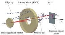
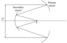
Design of Optical-mechanical System of Catadioptric Aerial Mapping Camera Based on Secondary Mirror Image Motion Compensation
Hongwei ZHANG, Rui QU, Weining CHEN, and Hongtao YANG
Aerial surveying and mapping is an important technical means of civil/military surveying and mapping, which can quickly obtain large-scale and high-precision scale mapping of the target area in a short period of time, and accurately obtain coordinate information of the target plane and elevation information on the map. The acquired information plays an important supporting role in digital city construction, land resources survey, military strategic planning, etc. With the development of aerial surveying and mapping technology, the requirements for aerial mapping cameras have been further improved. It is required that aerial mapping cameras can achieve wide width, high precision and large scale mapping. In order to meet the above requirements, the aerial mapping camera adopts scan imaging mode, but this imaging mechanism will introduce forward/scan image motion, which will affect the image quality. In order to satisfy the image stabilization accuracy of the aerial mapping camera, it is necessary to compensate the image motions. Therefore, a catadioptric aerial mapping camera based on secondary mirror image motion compensation is designed in this paper.Aiming at the dynamic image motion problem of the aerial mapping camera in the process of ground swing imaging, the vector aberration theory for a two-mirror telescopic systems is adopted. The secondary mirror is used as the image motion compensation element, and the comprehensive image motion compensation of the aerial mapping camera is realized through the secondary mirror multi-dimensional motion. However, in the process of compensating the image motion, the secondary mirror will be eccentric and inclined, which will cause the secondary mirror to be off-axis and affect the image quality. Therefore, a misalignment optical system model is established to study the relationship between the deviation vector of the secondary mirror field and the misalignment of the secondary mirror field, and the influence of the secondary mirror motion on the image quality is analyzed. Meanwhile, a design example of the optical-mechanical system of the catadioptric aerial mapping camera based on the secondary mirror image motion compensation is given. The effective focal length of the optical system is 450 mm, and the working spectrum is 435~900 nm. The field of view of the optical system is 4.17×3.13, and the F-number is 4.2. In the design process, the optical-mechanical system of aerial mapping camera adopts non-thermal design to adapt to the working environment of -40 ℃~60 ℃.In order to verify the image motion compensation ability of multi-dimensional motion of the optical element, an experimental platform is built to conduct laboratory imaging tests and field imaging tests on the aerial mapping camera. The laboratory imaging test results show that the dynamic resolution of the aerial mapping camera using the image motion compensation technology can reach 74 lp/mm, and the image motion compensation accuracy is better than 0.5 pixels, which meets the design expectation. In addition, the field imaging test results show that compared with disable image motion compensation function, the aerial survey camera with enable image motion compensation function can acquire sharp edges, clear images, and image quality can meet the expected requirements. Therefore, the camera has the advantages of high accuracy of image motion compensation, compact volume and high reliability, which lays a theoretical foundation for the direction of light and small, high precision and large scale mapping. Aerial surveying and mapping is an important technical means of civil/military surveying and mapping, which can quickly obtain large-scale and high-precision scale mapping of the target area in a short period of time, and accurately obtain coordinate information of the target plane and elevation information on the map. The acquired information plays an important supporting role in digital city construction, land resources survey, military strategic planning, etc. With the development of aerial surveying and mapping technology, the requirements for aerial mapping cameras have been further improved. It is required that aerial mapping cameras can achieve wide width, high precision and large scale mapping. In order to meet the above requirements, the aerial mapping camera adopts scan imaging mode, but this imaging mechanism will introduce forward/scan image motion, which will affect the image quality. In order to satisfy the image stabilization accuracy of the aerial mapping camera, it is necessary to compensate the image motions. Therefore, a catadioptric aerial mapping camera based on secondary mirror image motion compensation is designed in this paper.Aiming at the dynamic image motion problem of the aerial mapping camera in the process of ground swing imaging, the vector aberration theory for a two-mirror telescopic systems is adopted. The secondary mirror is used as the image motion compensation element, and the comprehensive image motion compensation of the aerial mapping camera is realized through the secondary mirror multi-dimensional motion. However, in the process of compensating the image motion, the secondary mirror will be eccentric and inclined, which will cause the secondary mirror to be off-axis and affect the image quality. Therefore, a misalignment optical system model is established to study the relationship between the deviation vector of the secondary mirror field and the misalignment of the secondary mirror field, and the influence of the secondary mirror motion on the image quality is analyzed. Meanwhile, a design example of the optical-mechanical system of the catadioptric aerial mapping camera based on the secondary mirror image motion compensation is given. The effective focal length of the optical system is 450 mm, and the working spectrum is 435~900 nm. The field of view of the optical system is 4.17×3.13, and the F-number is 4.2. In the design process, the optical-mechanical system of aerial mapping camera adopts non-thermal design to adapt to the working environment of -40 ℃~60 ℃.In order to verify the image motion compensation ability of multi-dimensional motion of the optical element, an experimental platform is built to conduct laboratory imaging tests and field imaging tests on the aerial mapping camera. The laboratory imaging test results show that the dynamic resolution of the aerial mapping camera using the image motion compensation technology can reach 74 lp/mm, and the image motion compensation accuracy is better than 0.5 pixels, which meets the design expectation. In addition, the field imaging test results show that compared with disable image motion compensation function, the aerial survey camera with enable image motion compensation function can acquire sharp edges, clear images, and image quality can meet the expected requirements. Therefore, the camera has the advantages of high accuracy of image motion compensation, compact volume and high reliability, which lays a theoretical foundation for the direction of light and small, high precision and large scale mapping.
Acta Photonica Sinica
- Publication Date: Feb. 25, 2024
- Vol. 53, Issue 2, 0222001 (2024)


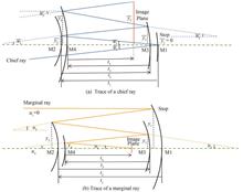
Automatic Design Method for the Off-axis Four-mirror Initial Arrangement Using Seidel Aberration Theory
Liwei ZHU, Lei YANG, Jie CHEN, Wenping ZHANG, Shiliang GUO, and Hongbo XIE
Reflective optical systems are normally divided into two types: coaxial reflective module and off-axis reflective module. Although the coaxial reflective module is capable of achieving a long focal length, it also has several obvious drawbacks such limited field of view and low utilization efficiency of propagating light due to obscuration. On the contrary, the off-axis reflective module has the particular capabilities of long focal length, wide field of view and high spatial resolution in diverse applications. Generally, an off-axis reflective systems are normally created from a coaxial reflective system based on the Seidel aberration theory. What is more, an unobscured off-axis system is obtained by using an offset aperture stop, a biased field, or combining both. However, the coaxial reflective systems are often far from the final off-axis reflective systems. Therefore, optimizing the coaxial reflective system without particularly constructing often costs much calculation time, and it is easy to fall into a local optimal solution during the optimization process.This paper proposes a new method for establishing the initial structure of an off-axis four-mirror optical system. At the beginning of the design, we chose a reasonably biased field to obtain off-axis reflective systems. Introduce the ray transmission matrix to simplify the paraxial ray tracing and calculate the Seidel aberration by tracing the chief and marginal ray. The Seidel aberration we obtained is a function including the radius of curvature and the mirror spacing. The traditional method of solving the initial structure is to make the Seidel aberration zero. When many constraints are defined, there may be no solution for all Seidel aberrations to be zero. This problem can be transformed into an optimization problem for solving the objective function. The objective function is to minimize the sum of the absolute values of the five primary aberration coefficients while adding some constraints, such as the back focal length and focal length requirement. Particle Swarm Optimization (PSO) suits high-dimensional nonlinear optimization problems. Therefore, the PSO algorithm is used in this paper to optimize the objective function. However, the PSO algorithm is affected by many factors, among which the initial particle value greatly influences the final result. Therefore, generating many random initial points is adopted to analyze and compare the results and select the solution results with a small objective function value. After that, we use a biased field to select the unobscured system through the data interaction of MATLAB and CODE V.The specific algorithm process is as follows: an initial biased field is given in advance, and the particle swarm optimization algorithm solves the objective function to find multiple sets of feasible solutions. The calculated radius of curvature and mirror spacing are imported into CODE V. Then, we call the CODEV API through MATLAB to obtain the data of the corresponding point. Judging whether the initial structure satisfies the unobscured condition by calculating the distance between points and lines. If a suitable unobscured structure is not found, change the biased field, re-find the optimal solution, and re-judge whether the corresponding point-line position relationship is satisfied. Since the diameter of the entrance pupil and the field of view is small when constructing the initial structure, it is necessary to gradually expand the diameter of the entrance pupil and the view in the optimization stage to meet the requirements of the design parameters.Generally speaking, if there is a large difference between the initial and final design parameters, increasing the entrance pupil diameter and view manually will take much time. However, if the entrance pupil diameter and view are too large for each iteration, it will lead to falling into a local optimal solution or being unable to realize ray tracing. To solve the time-consuming problem of manually increasing the entrance pupil diameter and field of view, this paper combines MATLAB and CODE V software to avoid repetitive optimization processes. By calling CODE V API through MATLAB to achieve data interaction between the two software, MATLAB can modify system parameters (entrance pupil diameter, the field of view, etc.). At the same time, the program for optimizing the off-axis four-mirror is saved in the form of a macro file, which is convenient for realizing the optimization of the off-axis four-mirror by calling the macro file in MATLAB. Through this method, the system’s expansion from a small entrance pupil and a small field of view to a large entrance pupil and a large field can be realized more quickly and efficiently. At the same time, XY polynomials and high-order aspheric surfaces are introduced to correct high-order aberrations. The proposed automatic design method studied has certain theoretical and practical value in designing off-axis reflective systems. Reflective optical systems are normally divided into two types: coaxial reflective module and off-axis reflective module. Although the coaxial reflective module is capable of achieving a long focal length, it also has several obvious drawbacks such limited field of view and low utilization efficiency of propagating light due to obscuration. On the contrary, the off-axis reflective module has the particular capabilities of long focal length, wide field of view and high spatial resolution in diverse applications. Generally, an off-axis reflective systems are normally created from a coaxial reflective system based on the Seidel aberration theory. What is more, an unobscured off-axis system is obtained by using an offset aperture stop, a biased field, or combining both. However, the coaxial reflective systems are often far from the final off-axis reflective systems. Therefore, optimizing the coaxial reflective system without particularly constructing often costs much calculation time, and it is easy to fall into a local optimal solution during the optimization process.This paper proposes a new method for establishing the initial structure of an off-axis four-mirror optical system. At the beginning of the design, we chose a reasonably biased field to obtain off-axis reflective systems. Introduce the ray transmission matrix to simplify the paraxial ray tracing and calculate the Seidel aberration by tracing the chief and marginal ray. The Seidel aberration we obtained is a function including the radius of curvature and the mirror spacing. The traditional method of solving the initial structure is to make the Seidel aberration zero. When many constraints are defined, there may be no solution for all Seidel aberrations to be zero. This problem can be transformed into an optimization problem for solving the objective function. The objective function is to minimize the sum of the absolute values of the five primary aberration coefficients while adding some constraints, such as the back focal length and focal length requirement. Particle Swarm Optimization (PSO) suits high-dimensional nonlinear optimization problems. Therefore, the PSO algorithm is used in this paper to optimize the objective function. However, the PSO algorithm is affected by many factors, among which the initial particle value greatly influences the final result. Therefore, generating many random initial points is adopted to analyze and compare the results and select the solution results with a small objective function value. After that, we use a biased field to select the unobscured system through the data interaction of MATLAB and CODE V.The specific algorithm process is as follows: an initial biased field is given in advance, and the particle swarm optimization algorithm solves the objective function to find multiple sets of feasible solutions. The calculated radius of curvature and mirror spacing are imported into CODE V. Then, we call the CODEV API through MATLAB to obtain the data of the corresponding point. Judging whether the initial structure satisfies the unobscured condition by calculating the distance between points and lines. If a suitable unobscured structure is not found, change the biased field, re-find the optimal solution, and re-judge whether the corresponding point-line position relationship is satisfied. Since the diameter of the entrance pupil and the field of view is small when constructing the initial structure, it is necessary to gradually expand the diameter of the entrance pupil and the view in the optimization stage to meet the requirements of the design parameters.Generally speaking, if there is a large difference between the initial and final design parameters, increasing the entrance pupil diameter and view manually will take much time. However, if the entrance pupil diameter and view are too large for each iteration, it will lead to falling into a local optimal solution or being unable to realize ray tracing. To solve the time-consuming problem of manually increasing the entrance pupil diameter and field of view, this paper combines MATLAB and CODE V software to avoid repetitive optimization processes. By calling CODE V API through MATLAB to achieve data interaction between the two software, MATLAB can modify system parameters (entrance pupil diameter, the field of view, etc.). At the same time, the program for optimizing the off-axis four-mirror is saved in the form of a macro file, which is convenient for realizing the optimization of the off-axis four-mirror by calling the macro file in MATLAB. Through this method, the system’s expansion from a small entrance pupil and a small field of view to a large entrance pupil and a large field can be realized more quickly and efficiently. At the same time, XY polynomials and high-order aspheric surfaces are introduced to correct high-order aberrations. The proposed automatic design method studied has certain theoretical and practical value in designing off-axis reflective systems.
Acta Photonica Sinica
- Publication Date: Jan. 25, 2024
- Vol. 53, Issue 1, 0122003 (2024)
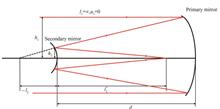
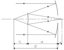
Optical Design of High-compression Ratio and Low-wavefront Error Gravitational Wave Detection Telescope
Rong LIANG, Xiaojun ZHOU, Chunbo ZOU, Huangrong XU, Chenxi LI, Tao YU, and Weixing YU
Since the first detection of gravitational wave, gravitational wave astronomy has advanced swiftly. As a crucial component of the detection system, the gravitational wave telescope is obviously crucial. The highly stable laser telescope with a low wavefront error and a high suppression ratio of stray light is a crucial medium for the detection of gravitational waves, as it must not only transmit energy in the order of watt to distant spacecraft, but also receive weak laser signals in the order of picowatt from other satellite base station located millions of kilometers away. Therefore, the backward stray light of the local telescope is required to reach 10-10 orders of the incident laser power. Considering the requirements of small size, light weight, and high compactness, it is clear that the benefits of a reflective system cannot be compared to those of a transmission design. In general, the coaxial Cassegrain structure and off-axis multi-mirror structure are utilized. The off-axis design is preferred over the coaxial design for gravitational wave telescopes due to advantages such as the ability to optimize multiple parameters, the absence of a central obstruction, and the high energy collection capacity. In this paper, based on the design of off-axis four-mirror and the theory of coaxial reflection system, we designed and optimized the telescope combined with the characteristics of high magnification, low wavefront error and high suppression ratio of stray light. In the capture field of view of ±200 μrad, we realized the compression ratio of 100 of telescope, and the entrance pupil diameter of the principle system is 300 mm, whose design result of wavefront error is less than of λ/80 because the actual outgoing wavefront error must be less than λ/40. The system distortion of the edge field is less than 0.056 9%. In order to verify the processing and alignment of the principle system as well as the ability of stray light suppression of it, a 0.5 times scale system is established beneath the system with a wavefront error less than λ/175. Internal stray light is suppressed by increasing the light turning angle between the tertiary mirror and quaternary mirror on the condition of low wavefront error of λ/80. The optimized deflection angle of the tertiary mirror is 5.5 degrees, and the tertiary mirror is the plane surface, which can significantly reduce the difficulty of processing and alignment. A simulation of stray light is applied to analyze the stray light of our designed telescope. The steps of stray light analysis consist of the following steps: 1) selection and optimization of the optical structure; 2) model setting of the corresponding reflection, scattering, and absorption surfaces; 3) stray light analysis of the entire system; 4) iterative optimization design; 5) fulfillment of the system's requirements. Therefore, we investigated the optical paths and power of the backscattered stray light. After positioning the field stop in the middle image plane between the secondary mirror and the tertiary mirror, the proportion of the stray light caused by the secondary mirror is the smallest. The stray light energy caused by the tertiary mirror and the quaternary mirror is the largest, which can reach more than 90%. The tolerance of the optical design is also analyzed, and the results of the analysis indicate that the tolerance of the parabolic primary mirror has the strongest impact on the wavefront error of the system. The principle system has a 90% cumulative probability wavefront error less than λ/40, which can satisfy the design requirement of gravitational wave detection and have the potential to play a significant role in future missions aimed at low wavefront error, high magnification and a high suppression ratio of stray light in the telescope while detecting gravitational waves. Since the first detection of gravitational wave, gravitational wave astronomy has advanced swiftly. As a crucial component of the detection system, the gravitational wave telescope is obviously crucial. The highly stable laser telescope with a low wavefront error and a high suppression ratio of stray light is a crucial medium for the detection of gravitational waves, as it must not only transmit energy in the order of watt to distant spacecraft, but also receive weak laser signals in the order of picowatt from other satellite base station located millions of kilometers away. Therefore, the backward stray light of the local telescope is required to reach 10-10 orders of the incident laser power. Considering the requirements of small size, light weight, and high compactness, it is clear that the benefits of a reflective system cannot be compared to those of a transmission design. In general, the coaxial Cassegrain structure and off-axis multi-mirror structure are utilized. The off-axis design is preferred over the coaxial design for gravitational wave telescopes due to advantages such as the ability to optimize multiple parameters, the absence of a central obstruction, and the high energy collection capacity. In this paper, based on the design of off-axis four-mirror and the theory of coaxial reflection system, we designed and optimized the telescope combined with the characteristics of high magnification, low wavefront error and high suppression ratio of stray light. In the capture field of view of ±200 μrad, we realized the compression ratio of 100 of telescope, and the entrance pupil diameter of the principle system is 300 mm, whose design result of wavefront error is less than of λ/80 because the actual outgoing wavefront error must be less than λ/40. The system distortion of the edge field is less than 0.056 9%. In order to verify the processing and alignment of the principle system as well as the ability of stray light suppression of it, a 0.5 times scale system is established beneath the system with a wavefront error less than λ/175. Internal stray light is suppressed by increasing the light turning angle between the tertiary mirror and quaternary mirror on the condition of low wavefront error of λ/80. The optimized deflection angle of the tertiary mirror is 5.5 degrees, and the tertiary mirror is the plane surface, which can significantly reduce the difficulty of processing and alignment. A simulation of stray light is applied to analyze the stray light of our designed telescope. The steps of stray light analysis consist of the following steps: 1) selection and optimization of the optical structure; 2) model setting of the corresponding reflection, scattering, and absorption surfaces; 3) stray light analysis of the entire system; 4) iterative optimization design; 5) fulfillment of the system's requirements. Therefore, we investigated the optical paths and power of the backscattered stray light. After positioning the field stop in the middle image plane between the secondary mirror and the tertiary mirror, the proportion of the stray light caused by the secondary mirror is the smallest. The stray light energy caused by the tertiary mirror and the quaternary mirror is the largest, which can reach more than 90%. The tolerance of the optical design is also analyzed, and the results of the analysis indicate that the tolerance of the parabolic primary mirror has the strongest impact on the wavefront error of the system. The principle system has a 90% cumulative probability wavefront error less than λ/40, which can satisfy the design requirement of gravitational wave detection and have the potential to play a significant role in future missions aimed at low wavefront error, high magnification and a high suppression ratio of stray light in the telescope while detecting gravitational waves.
Acta Photonica Sinica
- Publication Date: Jan. 25, 2024
- Vol. 53, Issue 1, 0122002 (2024)
Design of an Integrated Optical System for Detection and Imaging of Large Aperture and Long Focal Length Based on Continuous Zoom
Jinyang WEI, Xuyang LI, Longyu TAN, Hao YUAN, Zhiguang REN, Jiawen ZHAO, and Kaizhong YAO
In space target observation missions, there is a need for highly sensitive target detection and high-quality imaging. However, there is a significant disparity in the field of view between detection and imaging, and currently, two primary solutions are predominantly employed. One approach involves the design of two independent subsystems, while the other method utilizes a shared-aperture dual-channel design to integrate the functions of detection and imaging into a single system. However, designing two independent systems necessitates a substantial amount of space to accommodate these two subsystems, often exceeding the carrying capacity of most existing space optical payloads. On the other hand, adopting the shared-aperture dual-channel system requires additional electronic components and structural elements, with challenges during the assembly and calibration processes. This may potentially lead to uneven energy distribution issues. In order to achieve high sensitivity detection and precise identification of space targets, this paper introduces the design of an optical system based on a continuous zoom structure that balances a large aperture with a long focal length. This system aims to achieve short focal length and wide-field target detection, as well as long focal length and narrow-field target imaging. In terms of the design methodology, the inherent complexity of the system makes it challenging to obtain an ideal structure during the optimization process. Consequently, this system combines the structures of reflective mirrors and corrective lenses with a zoom structure through optical pupil matching. It employs two reflective mirrors to compress the optical path. During the zooming process, both the zooming components and compensating components move together to maintain the position of the image plane. At the intermediate zoom position, image quality is excellent, allowing for continuous target tracking. To address the issue of uneven energy distribution within the system, this optical system utilizes a shared-aperture detection and imaging integration structure. Furthermore, with an aperture size of 280 mm, the system can detect targets as faint as magnitude 14, effectively resolving the challenges associated with detecting faint and weak targets. The system operates within the spectral range of 450 nm to 850 nm and focal lengths ranging from 700 mm to 3 500 mm. At the detection end, the focal length is 700 mm, with an F-number of 2.5 and a field of view angle of 0.5°×0.5°. At the imaging end, the focal length varies from 1 400 mm to 3 500 mm, with F-numbers ranging from 5 to 12.5 and a field of view angle of 0.18°×0.18°. At the detection end, 80% of the optical spot's encircled energy is concentrated within 17.4 μm. At the imaging end, the edge field MTF is 0.36, approaching the diffraction limit, while at the intermediate zoom position, MTF values range from 0.31 to 0.36, ensuring consistent image quality during the zooming process. This system integrates the detection and imaging systems into a single unit, achieving shared-aperture functionality. After conducting tolerance analysis on the system, it was observed that under relatively loose tolerances, MTF degradation in both the sagittal and tangential directions is minimal. Moreover, at an 80% probability, the optical spot diameter is smaller than 18.4 μm for each field of view, indicating that the system maintains excellent detection and imaging performance even under these relaxed tolerance conditions. The zoom cam curve is a critical design parameter for zoom systems, and in this system, the cam curves for both the zoom and compensator groups have an apex angle of less than 30°, meeting the design requirements. This system offers strong detection capabilities, excellent image quality, a compact overall length, and a minimal zoom cam curve apex angle. In terms of structure and design objectives, it provides valuable insights for the future development of continuous tracking integrated optical systems for the detection and imaging of targets. In space target observation missions, there is a need for highly sensitive target detection and high-quality imaging. However, there is a significant disparity in the field of view between detection and imaging, and currently, two primary solutions are predominantly employed. One approach involves the design of two independent subsystems, while the other method utilizes a shared-aperture dual-channel design to integrate the functions of detection and imaging into a single system. However, designing two independent systems necessitates a substantial amount of space to accommodate these two subsystems, often exceeding the carrying capacity of most existing space optical payloads. On the other hand, adopting the shared-aperture dual-channel system requires additional electronic components and structural elements, with challenges during the assembly and calibration processes. This may potentially lead to uneven energy distribution issues. In order to achieve high sensitivity detection and precise identification of space targets, this paper introduces the design of an optical system based on a continuous zoom structure that balances a large aperture with a long focal length. This system aims to achieve short focal length and wide-field target detection, as well as long focal length and narrow-field target imaging. In terms of the design methodology, the inherent complexity of the system makes it challenging to obtain an ideal structure during the optimization process. Consequently, this system combines the structures of reflective mirrors and corrective lenses with a zoom structure through optical pupil matching. It employs two reflective mirrors to compress the optical path. During the zooming process, both the zooming components and compensating components move together to maintain the position of the image plane. At the intermediate zoom position, image quality is excellent, allowing for continuous target tracking. To address the issue of uneven energy distribution within the system, this optical system utilizes a shared-aperture detection and imaging integration structure. Furthermore, with an aperture size of 280 mm, the system can detect targets as faint as magnitude 14, effectively resolving the challenges associated with detecting faint and weak targets. The system operates within the spectral range of 450 nm to 850 nm and focal lengths ranging from 700 mm to 3 500 mm. At the detection end, the focal length is 700 mm, with an F-number of 2.5 and a field of view angle of 0.5°×0.5°. At the imaging end, the focal length varies from 1 400 mm to 3 500 mm, with F-numbers ranging from 5 to 12.5 and a field of view angle of 0.18°×0.18°. At the detection end, 80% of the optical spot's encircled energy is concentrated within 17.4 μm. At the imaging end, the edge field MTF is 0.36, approaching the diffraction limit, while at the intermediate zoom position, MTF values range from 0.31 to 0.36, ensuring consistent image quality during the zooming process. This system integrates the detection and imaging systems into a single unit, achieving shared-aperture functionality. After conducting tolerance analysis on the system, it was observed that under relatively loose tolerances, MTF degradation in both the sagittal and tangential directions is minimal. Moreover, at an 80% probability, the optical spot diameter is smaller than 18.4 μm for each field of view, indicating that the system maintains excellent detection and imaging performance even under these relaxed tolerance conditions. The zoom cam curve is a critical design parameter for zoom systems, and in this system, the cam curves for both the zoom and compensator groups have an apex angle of less than 30°, meeting the design requirements. This system offers strong detection capabilities, excellent image quality, a compact overall length, and a minimal zoom cam curve apex angle. In terms of structure and design objectives, it provides valuable insights for the future development of continuous tracking integrated optical systems for the detection and imaging of targets.
Acta Photonica Sinica
- Publication Date: Jan. 25, 2024
- Vol. 53, Issue 1, 0122001 (2024)
Design and Optimization of Dual-focal Vehicle Head-up Display Optical System Based on Single-optical Machine
Jinwei REN, Xiaowei CHEN, Bo WANG, Yan CAO, Yihan SUN, Xinyu LI, and Shenjiang WU
As society continues to progress, automobiles have become a common sight in households worldwide. However, the increase in the number of vehicles on the road has led to a series of traffic safety issues. As a result, automotive safety has become one of the most popular research topics worldwide. Among them, Head-Up Display (HUD) systems can be applied to cars, serving as an assistant to driving and improving driving safety. Through the use of a head-up display optical system, drivers can see virtual images that display important driving information and road conditions in the direction of their line of sight, eliminating the need to look down at instrument panel information and navigation information. This reduces driver distraction and improves driving safety. As HUD technology continues to advance and develop, it will gradually integrate with autonomous driving systems, becoming a standard feature in future high-tech vehicles. Nowadays, the technology of automotive HUD on the market is gradually maturing, mainly including Windshield HUD (W-HUD) and Augmented Reality HUD (AR-HUD). However, the current car-mounted HUD can only display virtual images on a single projection distance. When the driver changes the observation due to changes in vehicle speed, the visual focus distance needs to be adjusted to adapt to the HUD projection distance. Long-term and high-frequency adjustments can lead to eye fatigue for the driver. To address this issue, this paper proposes the design of a car-mounted binocular parallax optical system. Based on the current research status, a method of using a single DLP micro-projection machine to separate two images and generate two Projection Generating Units (PGUs) to display binocular virtual images for AR-HUD is proposed. According to the initial architecture of the HUD optical system, which is a coaxial reflection optical system, an off-axis reflection vehicle-mounted parallax display optical system is constructed by using an off-axis rotating reflection mirror. Then, by changing the object distance of the PGUs to the primary reflection mirror, the two free-form reflection mirrors are combined to construct an off-axis reflection binocular parallax vehicle-mounted display optical system, thereby ensuring the projection of two virtual images at different distances. The optical system uses a 5.74 inch DLP micro projector with an eyebox size of 130 mm×50 mm, a far projection field of view of 10°×3° and a near projection field of view of 4°×1°, and a virtual image projection distance of 3.8 m and 7.5 m. Image quality evaluation is analyzed and explained from the aspects of the point cloud diagram, MTF curve diagram, grid distortion, illumination curve diagram, and image simulation. The key to the optical system is tolerance analysis, which helps to determine the allowable limits of different manufacturing and alignment errors. Manufacturing and calibration errors can be reduced to an appropriate level without degrading the image quality of the optical system. If the tolerance requirements are too strict, it may increase the difficulty in processing and arranging the optical components and may also lead to unstable imaging quality during actual use. By designing the tolerance range of the curvature radius of the lens and the windshield usage area, the distance between lenses and the windshield usage area, the X-axis offset lens and the windshield usage area, the Y-axis offset lens and the windshield usage area, the axial rotation of the lens and the windshield usage area, and the axial rotation of the lens and the windshield usage area, the statistical results of the optical transfer function of the system's virtual image plane were obtained using Monte Carlo method with 1 000 randomly selected samples. It can be seen that at a spatial cutoff frequency of 4.42 1p/mm, more than 90% of the MTF of the optical system is greater than 0.63, indicating that the tolerance distribution of the system is reasonable, the tolerance capability is strong, and the design results are ideal. The design result of the dual-path AR-HUD optical system in this paper shows that, through software control, the near projection virtual image plane and the far projection virtual image plane can be displayed simultaneously or in a time-sharing manner, which improves the driver's visual experience. As society continues to progress, automobiles have become a common sight in households worldwide. However, the increase in the number of vehicles on the road has led to a series of traffic safety issues. As a result, automotive safety has become one of the most popular research topics worldwide. Among them, Head-Up Display (HUD) systems can be applied to cars, serving as an assistant to driving and improving driving safety. Through the use of a head-up display optical system, drivers can see virtual images that display important driving information and road conditions in the direction of their line of sight, eliminating the need to look down at instrument panel information and navigation information. This reduces driver distraction and improves driving safety. As HUD technology continues to advance and develop, it will gradually integrate with autonomous driving systems, becoming a standard feature in future high-tech vehicles. Nowadays, the technology of automotive HUD on the market is gradually maturing, mainly including Windshield HUD (W-HUD) and Augmented Reality HUD (AR-HUD). However, the current car-mounted HUD can only display virtual images on a single projection distance. When the driver changes the observation due to changes in vehicle speed, the visual focus distance needs to be adjusted to adapt to the HUD projection distance. Long-term and high-frequency adjustments can lead to eye fatigue for the driver. To address this issue, this paper proposes the design of a car-mounted binocular parallax optical system. Based on the current research status, a method of using a single DLP micro-projection machine to separate two images and generate two Projection Generating Units (PGUs) to display binocular virtual images for AR-HUD is proposed. According to the initial architecture of the HUD optical system, which is a coaxial reflection optical system, an off-axis reflection vehicle-mounted parallax display optical system is constructed by using an off-axis rotating reflection mirror. Then, by changing the object distance of the PGUs to the primary reflection mirror, the two free-form reflection mirrors are combined to construct an off-axis reflection binocular parallax vehicle-mounted display optical system, thereby ensuring the projection of two virtual images at different distances. The optical system uses a 5.74 inch DLP micro projector with an eyebox size of 130 mm×50 mm, a far projection field of view of 10°×3° and a near projection field of view of 4°×1°, and a virtual image projection distance of 3.8 m and 7.5 m. Image quality evaluation is analyzed and explained from the aspects of the point cloud diagram, MTF curve diagram, grid distortion, illumination curve diagram, and image simulation. The key to the optical system is tolerance analysis, which helps to determine the allowable limits of different manufacturing and alignment errors. Manufacturing and calibration errors can be reduced to an appropriate level without degrading the image quality of the optical system. If the tolerance requirements are too strict, it may increase the difficulty in processing and arranging the optical components and may also lead to unstable imaging quality during actual use. By designing the tolerance range of the curvature radius of the lens and the windshield usage area, the distance between lenses and the windshield usage area, the X-axis offset lens and the windshield usage area, the Y-axis offset lens and the windshield usage area, the axial rotation of the lens and the windshield usage area, and the axial rotation of the lens and the windshield usage area, the statistical results of the optical transfer function of the system's virtual image plane were obtained using Monte Carlo method with 1 000 randomly selected samples. It can be seen that at a spatial cutoff frequency of 4.42 1p/mm, more than 90% of the MTF of the optical system is greater than 0.63, indicating that the tolerance distribution of the system is reasonable, the tolerance capability is strong, and the design results are ideal. The design result of the dual-path AR-HUD optical system in this paper shows that, through software control, the near projection virtual image plane and the far projection virtual image plane can be displayed simultaneously or in a time-sharing manner, which improves the driver's visual experience.
Acta Photonica Sinica
- Publication Date: Aug. 25, 2023
- Vol. 52, Issue 8, 0822001 (2023)

Determination and Experimental Study of Three Kinds of Stray Light in the Coronagraph System
Yupeng HUANG, Hongxin ZHANG, Yue DING, and Taisheng WANG
The coronagraph is a scientific instrument developed to observe extremely faint coronal emission in the strong background of the solar disk. During the coronagraph observation and laboratory detection procedures, numerous non-imaging beams are present. The entrance of non-imaging beams into the detector has an adverse impact on the imaging contrast and these beams reaching the image plane are usually called stray light. In order to discern the subtle coronal signal, it is imperative for the coronagraph to effectively mitigate most forms of stray light present within the system. Due to the stark contrast in brightness between the corona and the solar photosphere, very strict requirements must be met in terms of the suppression of stray light to obtain reliable measurements. This paper primarily examines three forms of stray light within inner mask coronagraph systems as per the stipulations set forth by the requirements of the coronagraph, including the ghost images produced by the reflections from two surfaces of the objective, the scattering points from the objective, and the diffracted light from the aperture stop. The origins of the aforementioned three types of stray light can be attributed to the inherent characteristics of the solar corona system, and they can not be completely eliminated from the coronagraph itself. Therefore, alternative procedures must be implemented to effectively nullify the stray light prior to reaching the image plane. We simulate the coronagraph system using optical modeling software and plot the stray light propagation path within the optical system. Our analysis reveals that the propagation of the aforementioned three types of stray light in the optical system converges at multiple locations. Further, based on the corresponding propagation paths, we have established the respective intensity distribution patterns of the three types of stray light at their imaging location and the characteristics of these kinds of stray light are also analyzed. Upon conducting an in-depth analysis, it is discovered that the imaging locations of the three stray light types are in close proximity to each other, and exhibit similar imaging characteristics, resulting in significant interference to the detection process and the detection result of the system. Based on the simulation results, we summed up the causes of these stray lights and give the methods for detecting and mitigating these stray lights. At the same time, the corresponding experimental verification method is designed and a coronagraph with a field-of-view of ±1.08 R⊙~±2.5 R⊙(R⊙represents the radius of the sun), a working wavelength range of 530.3~637.4 nm, and a total length of 3 713.28 mm was used for experimental comparison, and feasibility of the methods is verified. The camera used for the final image plane in this study was the Dhyana 95 V2 back-illuminated sCMOS camera. It boasted an effective pixel count of 2 048×2 048, an effective imaging area of 22.5 mm×22.5 mm, and a pixel size of 11 μm×11 μm. The experimental results provide confirmation of the viability and efficacy of the aforementioned determination method. Moreover, the shelter and ghost image shielding structure is designed to mitigate the effects of stray light. The level of stray light was measured following the suppression, and it was found to meet the observation criteria. The stray light analysis and suppression implemented in this study broaden the array of available methods for mitigating stray light in coronal instrument systems, enhancing the efficiency and precision of laboratory-based detection of the coronagraph systems. The coronagraph is a scientific instrument developed to observe extremely faint coronal emission in the strong background of the solar disk. During the coronagraph observation and laboratory detection procedures, numerous non-imaging beams are present. The entrance of non-imaging beams into the detector has an adverse impact on the imaging contrast and these beams reaching the image plane are usually called stray light. In order to discern the subtle coronal signal, it is imperative for the coronagraph to effectively mitigate most forms of stray light present within the system. Due to the stark contrast in brightness between the corona and the solar photosphere, very strict requirements must be met in terms of the suppression of stray light to obtain reliable measurements. This paper primarily examines three forms of stray light within inner mask coronagraph systems as per the stipulations set forth by the requirements of the coronagraph, including the ghost images produced by the reflections from two surfaces of the objective, the scattering points from the objective, and the diffracted light from the aperture stop. The origins of the aforementioned three types of stray light can be attributed to the inherent characteristics of the solar corona system, and they can not be completely eliminated from the coronagraph itself. Therefore, alternative procedures must be implemented to effectively nullify the stray light prior to reaching the image plane. We simulate the coronagraph system using optical modeling software and plot the stray light propagation path within the optical system. Our analysis reveals that the propagation of the aforementioned three types of stray light in the optical system converges at multiple locations. Further, based on the corresponding propagation paths, we have established the respective intensity distribution patterns of the three types of stray light at their imaging location and the characteristics of these kinds of stray light are also analyzed. Upon conducting an in-depth analysis, it is discovered that the imaging locations of the three stray light types are in close proximity to each other, and exhibit similar imaging characteristics, resulting in significant interference to the detection process and the detection result of the system. Based on the simulation results, we summed up the causes of these stray lights and give the methods for detecting and mitigating these stray lights. At the same time, the corresponding experimental verification method is designed and a coronagraph with a field-of-view of ±1.08 R⊙~±2.5 R⊙(R⊙represents the radius of the sun), a working wavelength range of 530.3~637.4 nm, and a total length of 3 713.28 mm was used for experimental comparison, and feasibility of the methods is verified. The camera used for the final image plane in this study was the Dhyana 95 V2 back-illuminated sCMOS camera. It boasted an effective pixel count of 2 048×2 048, an effective imaging area of 22.5 mm×22.5 mm, and a pixel size of 11 μm×11 μm. The experimental results provide confirmation of the viability and efficacy of the aforementioned determination method. Moreover, the shelter and ghost image shielding structure is designed to mitigate the effects of stray light. The level of stray light was measured following the suppression, and it was found to meet the observation criteria. The stray light analysis and suppression implemented in this study broaden the array of available methods for mitigating stray light in coronal instrument systems, enhancing the efficiency and precision of laboratory-based detection of the coronagraph systems.
Acta Photonica Sinica
- Publication Date: Nov. 25, 2023
- Vol. 52, Issue 11, 1122003 (2023)
Design and Verification of Automatic Alignment System for Batch Space Refractive Lenses
Yang HUANG, Chao ZHANG, Zhuwei ZHANG, Shengjie ZHANG, and Chengguang CUI
In order to obtain wide-range and high-precision remote sensing information, aerospace powers such as China, the United States, and many other European countries have adopted large-scale, multi orbit, and global coverage satellite deployment methods, and the space cameras are also developing in batches. Compared to traditional remote sensing cameras that only require some traditional imaging performance indicators, batch space cameras increase the requirements for shorter manufacturing cycles and higher image quality uniformity between batches. Due to the characteristics of large field of view, small size, and low cost, refractive lenses have been widely used in batch space cameras. At present, the precision centering error method is mainly used for the adjustment of space refractive lenses at home and abroad. The adjustment process is highly dependent on manual skills and experience. In addition, due to the random deviations of batch materials, lens processing accuracy, lenses adjustment tolerance and other factors, it is difficult to achieve high image quality uniformity of batch lenses while ensuring short adjustment cycle. Therefore, it is necessary to improve the assembly efficiency and quality uniformity of batch lenses by introducing more practical automatic alignment system.With the construction idea of“structural integration, adjustment automation, detection online and correction autonomy”, an automatic lenses alignment system with functions of automatic adjustment, online detection, automatic analysis and correction of wavefront aberrations was developed. Firstly, an automatic lens adjustment method was designed based on the centering error measurement. The measurement values of lens mis-adjustment were converted to the linear movement values of the adjustment devices by coordinate projection, and the automatic adjustment was realized by the combined movements of the adjustment devices driven by the motor. Then, according to the automatic adjustment mode, the lenses structure was designed, and the stability of structural mechanics was analyzed by finite element model. Finally, an integrated platform for lenses adjustment and measurement was built, and a wavefront aberrations correction module was designed. According to the results of system wavefront aberrations measurement, the lenses degree of freedom adjustments were analyzed automatically, and the positions of the lenses were adjusted by driving the adjustment devices to compensate the image quality. The high uniformity of image quality between batches was guaranteed by correcting residual wavefront aberrations equally.In the experiment, 20 refractive lenses were aligned by this automatic alignment system. Taking the first lenses alignment as an example, firstly, during the automatic adjustment process, the lens mis-adjustment values could be controlled within tolerance by two position adjustments. Then, through online detection of lenses wavefront aberrations and MTF, the degrees of freedom adjustments for lenses were calculated automatically. Finally, by automatically correcting residual wavefront aberrations, the wavefront aberrations of the lenses in 5 fields of view were evenly improved. The average MTF (@33 lp/mm) at the lenses edge fields of view was increased from 0.616 to 0.665, and the maximum deviation of MTF was decreased from 0.086 to 0.003, which laid the foundation for the image quality uniformity in the corresponding field of view between batches. The results of 20 lenses alignment and measurement show that the use of automatic alignment system can significantly reduce manual operations, and the alignment cycle is reduced to 3 days per set. By automatic adjustment, the accuracy of lenses tilt, decenter and distance is respectively better than 10″, 5 μm and 5 μm. Furthermore, after automatic correction of wavefront aberrations, the maximum deviation of MTF in the corresponding field of view between batches is 0.026. 20 lenses alignment results meet the requirements.In this study, an automatic alignment system for batch space refractive lenses was developed, which solved the problem that traditional methods can't meet the requirements of short manufacturing cycles and high image quality uniformity between batches, and realized automatic closed-loop control of lens adjustment, image quality detection, degree of freedom adjustment analysis and wavefront aberration correction. It provides an efficient and automatic development way for the batch space refractive lenses. The principles and methods can be extended to the alignment of reflective optical system, and have important reference significance for the design and development of other similar products. In order to obtain wide-range and high-precision remote sensing information, aerospace powers such as China, the United States, and many other European countries have adopted large-scale, multi orbit, and global coverage satellite deployment methods, and the space cameras are also developing in batches. Compared to traditional remote sensing cameras that only require some traditional imaging performance indicators, batch space cameras increase the requirements for shorter manufacturing cycles and higher image quality uniformity between batches. Due to the characteristics of large field of view, small size, and low cost, refractive lenses have been widely used in batch space cameras. At present, the precision centering error method is mainly used for the adjustment of space refractive lenses at home and abroad. The adjustment process is highly dependent on manual skills and experience. In addition, due to the random deviations of batch materials, lens processing accuracy, lenses adjustment tolerance and other factors, it is difficult to achieve high image quality uniformity of batch lenses while ensuring short adjustment cycle. Therefore, it is necessary to improve the assembly efficiency and quality uniformity of batch lenses by introducing more practical automatic alignment system.With the construction idea of“structural integration, adjustment automation, detection online and correction autonomy”, an automatic lenses alignment system with functions of automatic adjustment, online detection, automatic analysis and correction of wavefront aberrations was developed. Firstly, an automatic lens adjustment method was designed based on the centering error measurement. The measurement values of lens mis-adjustment were converted to the linear movement values of the adjustment devices by coordinate projection, and the automatic adjustment was realized by the combined movements of the adjustment devices driven by the motor. Then, according to the automatic adjustment mode, the lenses structure was designed, and the stability of structural mechanics was analyzed by finite element model. Finally, an integrated platform for lenses adjustment and measurement was built, and a wavefront aberrations correction module was designed. According to the results of system wavefront aberrations measurement, the lenses degree of freedom adjustments were analyzed automatically, and the positions of the lenses were adjusted by driving the adjustment devices to compensate the image quality. The high uniformity of image quality between batches was guaranteed by correcting residual wavefront aberrations equally.In the experiment, 20 refractive lenses were aligned by this automatic alignment system. Taking the first lenses alignment as an example, firstly, during the automatic adjustment process, the lens mis-adjustment values could be controlled within tolerance by two position adjustments. Then, through online detection of lenses wavefront aberrations and MTF, the degrees of freedom adjustments for lenses were calculated automatically. Finally, by automatically correcting residual wavefront aberrations, the wavefront aberrations of the lenses in 5 fields of view were evenly improved. The average MTF (@33 lp/mm) at the lenses edge fields of view was increased from 0.616 to 0.665, and the maximum deviation of MTF was decreased from 0.086 to 0.003, which laid the foundation for the image quality uniformity in the corresponding field of view between batches. The results of 20 lenses alignment and measurement show that the use of automatic alignment system can significantly reduce manual operations, and the alignment cycle is reduced to 3 days per set. By automatic adjustment, the accuracy of lenses tilt, decenter and distance is respectively better than 10″, 5 μm and 5 μm. Furthermore, after automatic correction of wavefront aberrations, the maximum deviation of MTF in the corresponding field of view between batches is 0.026. 20 lenses alignment results meet the requirements.In this study, an automatic alignment system for batch space refractive lenses was developed, which solved the problem that traditional methods can't meet the requirements of short manufacturing cycles and high image quality uniformity between batches, and realized automatic closed-loop control of lens adjustment, image quality detection, degree of freedom adjustment analysis and wavefront aberration correction. It provides an efficient and automatic development way for the batch space refractive lenses. The principles and methods can be extended to the alignment of reflective optical system, and have important reference significance for the design and development of other similar products.
Acta Photonica Sinica
- Publication Date: Nov. 25, 2023
- Vol. 52, Issue 11, 1122002 (2023)
Stable Structure of a Near-infrared Doppler Asymmetric Spatial Heterodyne Interferometer
Jian SUN, Yutao FENG, Chenguang CHANG, Wei WANG, Juan LI, and Bingliang HU
The mounting for a space-borne Doppler Asymmetric Spatial Heterodyne (DASH) interferometer, which is a key part of the space-borne DASH wind instrument, should be able to withstand the mechanical and thermal conditions of being space-borne. As spectral resolution increases, the size of the DASH interferometer increases. The stable rugged support structure for a large-sized interferometer has become a key issue. By far, the vast majority of the vibrational energy is produced at lower frequencies. Therefore, in order to improve mechanical performance, an effort can be made to ensure that the lowest natural frequency of the mounting structure is as high as possible. In existing approaches, the natural frequency of the assembly can be increased by increasing the adhesive area. However, the (metal-to-glass) gluing surface tension breaks during the vibration tests because of the lower natural frequency. In this paper, a novel, and stable support structure is proposed, with its effectiveness exemplified for a Near-Infrared (NIR) DASH interferometer. Based on the principle of DASH interferometer technique, the materials and dimensions of the optical components were selected to compensate for the phase shift at the fringes as the arms expand with temperature, which improves the optical components' thermal stability. The mathematical model of a structure was established, and the detail optimization process was designed. Parameters affecting the spring constants were analyzed. The parameters of the structure were optimized by requiring the maximum mechanical stress of the structure and maximum shear stress at the gluing surface to be less than the strength value. The spring constants were designed to adjust the natural frequency of the DASH interferometer assembly and improve the mechanical stability. The mathematical model results show that the lower spring is much stiffer than the top spring. The maximum shear stress of the structure was 48 MPa. The maximum shear stress at the gluing surface was 1.4 MPa. The bending deformations of the gluing surfaces were less than 1 μm. The Finite Element Analysis (FEA) results show that the maximum stresses of mechanical components and optical components were 65.56 MPa and 0.56 MPa, which are less than the tensile strength of the material. The maximum shear stress at metal-to-glass gluing surfaces was 3.4 MPa. The safety margin was 3.4. The maximum shear stress at the glass-to-glass gluing surface was 0.16 MPa. The safety margin was 83.3. All values have a high safety margin. The FEA results were consistent with the model calculation results. As the DASH interferometer is thermally stabilized about 5 ℃ above the wind instrument temperature, the Finite Element Model(FEM)of the DASH interferometer assembly was established to analyze the thermal stability. Under the environmental temperature change of 5 ℃, the Surface Shape Error (RMS) of beam splitters was 1.671 nm. The interferogram distortion caused by thermal stress can be ignored. The vibration test results indicate that the relative error of natural frequencies between the FEM and sine sweep test was less than 4%. The results from FEA and vibration tests agree with the model calculation results. The optical results indicate that the fringe frequency did not change (the number of fringes is 50) before and after the vibration test, which directly reveals that there was no breakage in the gluing surfaces (metal-to-glass gluing and glass-to-glass gluing), and the interferometer assembly remained undamaged. The phase shift was caused by the location accuracy of the DASH interferometer assembly in the optical system. Compared with existing methods, the mechanical performance was improved. The proposed structure can meet the requirements of the launch environment. Moreover, the proposed design of the stable support structure can be used in other interferometers. And the structure was used to mount a short infrared wave DASH interferometer, which is larger than NIR DASH interferometer. The mounting for a space-borne Doppler Asymmetric Spatial Heterodyne (DASH) interferometer, which is a key part of the space-borne DASH wind instrument, should be able to withstand the mechanical and thermal conditions of being space-borne. As spectral resolution increases, the size of the DASH interferometer increases. The stable rugged support structure for a large-sized interferometer has become a key issue. By far, the vast majority of the vibrational energy is produced at lower frequencies. Therefore, in order to improve mechanical performance, an effort can be made to ensure that the lowest natural frequency of the mounting structure is as high as possible. In existing approaches, the natural frequency of the assembly can be increased by increasing the adhesive area. However, the (metal-to-glass) gluing surface tension breaks during the vibration tests because of the lower natural frequency. In this paper, a novel, and stable support structure is proposed, with its effectiveness exemplified for a Near-Infrared (NIR) DASH interferometer. Based on the principle of DASH interferometer technique, the materials and dimensions of the optical components were selected to compensate for the phase shift at the fringes as the arms expand with temperature, which improves the optical components' thermal stability. The mathematical model of a structure was established, and the detail optimization process was designed. Parameters affecting the spring constants were analyzed. The parameters of the structure were optimized by requiring the maximum mechanical stress of the structure and maximum shear stress at the gluing surface to be less than the strength value. The spring constants were designed to adjust the natural frequency of the DASH interferometer assembly and improve the mechanical stability. The mathematical model results show that the lower spring is much stiffer than the top spring. The maximum shear stress of the structure was 48 MPa. The maximum shear stress at the gluing surface was 1.4 MPa. The bending deformations of the gluing surfaces were less than 1 μm. The Finite Element Analysis (FEA) results show that the maximum stresses of mechanical components and optical components were 65.56 MPa and 0.56 MPa, which are less than the tensile strength of the material. The maximum shear stress at metal-to-glass gluing surfaces was 3.4 MPa. The safety margin was 3.4. The maximum shear stress at the glass-to-glass gluing surface was 0.16 MPa. The safety margin was 83.3. All values have a high safety margin. The FEA results were consistent with the model calculation results. As the DASH interferometer is thermally stabilized about 5 ℃ above the wind instrument temperature, the Finite Element Model(FEM)of the DASH interferometer assembly was established to analyze the thermal stability. Under the environmental temperature change of 5 ℃, the Surface Shape Error (RMS) of beam splitters was 1.671 nm. The interferogram distortion caused by thermal stress can be ignored. The vibration test results indicate that the relative error of natural frequencies between the FEM and sine sweep test was less than 4%. The results from FEA and vibration tests agree with the model calculation results. The optical results indicate that the fringe frequency did not change (the number of fringes is 50) before and after the vibration test, which directly reveals that there was no breakage in the gluing surfaces (metal-to-glass gluing and glass-to-glass gluing), and the interferometer assembly remained undamaged. The phase shift was caused by the location accuracy of the DASH interferometer assembly in the optical system. Compared with existing methods, the mechanical performance was improved. The proposed structure can meet the requirements of the launch environment. Moreover, the proposed design of the stable support structure can be used in other interferometers. And the structure was used to mount a short infrared wave DASH interferometer, which is larger than NIR DASH interferometer.
Acta Photonica Sinica
- Publication Date: Nov. 25, 2023
- Vol. 52, Issue 11, 1122001 (2023)
Design and Optimization of Image Slicer in Coherent Dispersive Spectrometer
Yidong WANG, Ruyi WEI, Zhengmao XIE, Kai ZHANG, and Shasha CHEN
Image slicer is an important optical device in astronomical observation spectrometer. It can effectively improve the resolution and energy transmittance of the instrument. The image slicer can divide the circular image spot into strips and arrange the strips in a straight line, so that all the image spots can pass through the spectrometer slit. Image slicers are commonly used in astronomical observation spectrometers to help instruments achieve high spectral resolution with medium apertures. Image slicers can be divided into 4 categories according to their working principles. Among them, Bowen-Walraven type is the most widely used image slicer type. Coherent dispersive spectroscopy is a technique that combines an interferometer and an intermediate resolution spectrometer. It measures the phase change of the interference fringes of the stellar spectral lines after the Doppler frequency shift, and calculates the radial velocity change of the star and the mass of the planet. Since the phase difference has a certain amplification factor relative to the wavelength offset, when the spectral resolution is the same, the radial velocity detection accuracy of the coherent dispersion technique can be greatly improved compared with the traditional echelle grating method.This paper is based on the coherent dispersive spectrometer used to detect exoplanets by the radial velocity method. The radial velocity detection accuracy is expected to be less than 1 m/s, and the detection target is K/M dwarf stars. The structure of the coherent dispersion spectrometer consists of collimating mirror, Sagnac interferometer, imaging mirror group, image slicer, relay mirror group, slit, dispersion grating and CCD. The working spectral range of the spectrometer is 660~900 nm, the system transmittance at the center wavelength is about 0.4, and the spectral resolution is 0.03 nm. In order to meet the requirements of energy utilization and spectral resolution, the system needs to use the image slicer to realize the target surface multiplexing of the CCD and the reasonable matching of the numerical aperture. Therefore, setting a reasonable number of segmented images and the F number of the imaging lens group to achieve a good segmentation effect is of great significance to the improvement of system performance.In order to reduce the influence of imaging defects on the system, two design schemes of the image slicer are modeled and calculated in this paper. This paper also studies the relationship between the thickness of the reflective cavity and the incident angle and the defocusing and object point repetition, and deduces the general design formula of the thickness of the optical reflective cavity, which provides an important reference for the design of the image slicer. In addition, for the coherent dispersive spectrometer system used for exoplanet detection, this paper simulates the defocus and object point repetition under different F numbers and segmentation numbers. By analyzing the simulation results, the following conclusions are obtained: 1) With the increase of the F number and the number of divisions, the defocus amount increases significantly, and the defocus phenomenon becomes more obvious. 2) The phenomenon of object point repetition appears in all simulation results, which is determined by the design principle and cannot be avoided. 3) The design results of the two design schemes are relatively similar. Since the optical path in the Bowen?Walraven type design is propagated through the glass medium, the defocus amount is larger than that of the simplified type. The ratio of the diffuse spot diameter to the image spot diameter is the same for both methods. Based on the comprehensive simulation effect, and considering the requirements of the coherent dispersion spectrometer system, it can be considered that the imaging defects are relatively balanced and the energy loss is less when the star image is divided into 4 under the condition of F/24, which is a relatively suitable solution. In addition, since the defocus amount of the simplified type is smaller, and only the flat mirror needs to be processed, the cost is lower, so the simplified design scheme can be adopted.The work of this paper plays an important role in achieving the expected performance of the instrument, and provides a reference and application reference for other high-resolution spectrometers to determine system parameters. At the same time, the work of this paper provides a general design idea for Bowen?Walraven and simplified image slicer design, which is instructive for optimizing the design process of image slicer. Image slicer is an important optical device in astronomical observation spectrometer. It can effectively improve the resolution and energy transmittance of the instrument. The image slicer can divide the circular image spot into strips and arrange the strips in a straight line, so that all the image spots can pass through the spectrometer slit. Image slicers are commonly used in astronomical observation spectrometers to help instruments achieve high spectral resolution with medium apertures. Image slicers can be divided into 4 categories according to their working principles. Among them, Bowen-Walraven type is the most widely used image slicer type. Coherent dispersive spectroscopy is a technique that combines an interferometer and an intermediate resolution spectrometer. It measures the phase change of the interference fringes of the stellar spectral lines after the Doppler frequency shift, and calculates the radial velocity change of the star and the mass of the planet. Since the phase difference has a certain amplification factor relative to the wavelength offset, when the spectral resolution is the same, the radial velocity detection accuracy of the coherent dispersion technique can be greatly improved compared with the traditional echelle grating method.This paper is based on the coherent dispersive spectrometer used to detect exoplanets by the radial velocity method. The radial velocity detection accuracy is expected to be less than 1 m/s, and the detection target is K/M dwarf stars. The structure of the coherent dispersion spectrometer consists of collimating mirror, Sagnac interferometer, imaging mirror group, image slicer, relay mirror group, slit, dispersion grating and CCD. The working spectral range of the spectrometer is 660~900 nm, the system transmittance at the center wavelength is about 0.4, and the spectral resolution is 0.03 nm. In order to meet the requirements of energy utilization and spectral resolution, the system needs to use the image slicer to realize the target surface multiplexing of the CCD and the reasonable matching of the numerical aperture. Therefore, setting a reasonable number of segmented images and the F number of the imaging lens group to achieve a good segmentation effect is of great significance to the improvement of system performance.In order to reduce the influence of imaging defects on the system, two design schemes of the image slicer are modeled and calculated in this paper. This paper also studies the relationship between the thickness of the reflective cavity and the incident angle and the defocusing and object point repetition, and deduces the general design formula of the thickness of the optical reflective cavity, which provides an important reference for the design of the image slicer. In addition, for the coherent dispersive spectrometer system used for exoplanet detection, this paper simulates the defocus and object point repetition under different F numbers and segmentation numbers. By analyzing the simulation results, the following conclusions are obtained: 1) With the increase of the F number and the number of divisions, the defocus amount increases significantly, and the defocus phenomenon becomes more obvious. 2) The phenomenon of object point repetition appears in all simulation results, which is determined by the design principle and cannot be avoided. 3) The design results of the two design schemes are relatively similar. Since the optical path in the Bowen?Walraven type design is propagated through the glass medium, the defocus amount is larger than that of the simplified type. The ratio of the diffuse spot diameter to the image spot diameter is the same for both methods. Based on the comprehensive simulation effect, and considering the requirements of the coherent dispersion spectrometer system, it can be considered that the imaging defects are relatively balanced and the energy loss is less when the star image is divided into 4 under the condition of F/24, which is a relatively suitable solution. In addition, since the defocus amount of the simplified type is smaller, and only the flat mirror needs to be processed, the cost is lower, so the simplified design scheme can be adopted.The work of this paper plays an important role in achieving the expected performance of the instrument, and provides a reference and application reference for other high-resolution spectrometers to determine system parameters. At the same time, the work of this paper provides a general design idea for Bowen?Walraven and simplified image slicer design, which is instructive for optimizing the design process of image slicer.
Acta Photonica Sinica
- Publication Date: Sep. 25, 2022
- Vol. 51, Issue 9, 0922002 (2022)
Design of a Solar-blind Ultraviolet Imaging System for Corona Detection
Suhao CHEN, Bo LÜ, Weiqi LIU, Rui FENG, and Zhonglun WEI
During real-time monitoring of high voltage corona discharge, the solar radiation intensity is much higher than the radiation generated by corona discharges, which will interfere with the detection process. However, due to the absorption of the earth's ozone layer, the radiation intensity of the sun's radiation to the ground becomes very weak in the solar-blind ultraviolet band of 240~280 nm. Observing high-voltage wires in this band can reduce the interference of the environment, thereby improving the imaging contrast and reducing the false detection rate. In order to expand the detection range and improve the detection accuracy of the solar-blind UV imaging system, the optical system needs to have a higher resolution while ensuring a larger field of view. In this paper, a solar-blind ultraviolet optical system with a large field of view, large relative aperture and high resolution is designed. We have formulated the design index according to user needs, and selected an anti-telephoto lens as the initial structure according to the design index requirements. During optimization, we first replaced the lens material with fused silica and calcium fluoride materials commonly used in the ultraviolet band. According to the principle of chromatic aberration correction, the positive lens is replaced by calcium fluoride with a large Abbe number, and the negative lens is replaced by fused silica with a small Abbe number. The refractive index of these two materials is low and the Abbe number difference is small in the solar-blind ultraviolet band, which is not suitable for chromatic aberration correction, and the typical achromatic structure doublet lenses can not transmit ultraviolet radiation, so we added two sets of double separation structures to correct chromatic aberration. Due to the high requirements for the surface roughness of the lens in the ultraviolet band, the limitation of materials and apertures, and the consideration of technological difficulty, no aspherical lens was introduced in this design. The final design uses 12 standard spherical lenses, with a total optical length of 90 mm, a full field of view of 56°, and a relative aperture of 1/2. In the full field of view, the distortion is less than 2.2%, the relative illumination is greater than 70%, the Modulation Transfer Function (MTF) of the system is greater than 0.65 at the spatial frequency of 110 lp/mm, and the optical system has good imaging quality. After that, we analyzed the thermal defocusing caused by the thermal deformation of the lens and lens barrel materials and the thermally induced refractive index change of the optical material in the temperature range of -20~60 ℃. The results show that the MTF of the system decreases significantly when the ambient temperature changes. The thermal defocus amount of the system has an approximate linear relationship with the temperature change, so we can use the passive mechanical compensation method to correct the thermal difference of the system. We use ABS plastic with high coefficient of linear expansion as the compensation lens barrel to compensate for thermal defocusing. The MTF of the compensated system is greater than 0.4 in the working temperature range, realizing athermal design. Finally, through reasonable tolerance allocation, the MTF of the tangential and sagittal directions of the system after processing and adjustment decreases relatively uniformly under the influence of tolerances. Under the probability of 80%, the MTF at the Nyquist sampling frequency of the system is greater than 0.35, and the system still maintains a high imaging quality, which meets the actual requirements of corona detection. During real-time monitoring of high voltage corona discharge, the solar radiation intensity is much higher than the radiation generated by corona discharges, which will interfere with the detection process. However, due to the absorption of the earth's ozone layer, the radiation intensity of the sun's radiation to the ground becomes very weak in the solar-blind ultraviolet band of 240~280 nm. Observing high-voltage wires in this band can reduce the interference of the environment, thereby improving the imaging contrast and reducing the false detection rate. In order to expand the detection range and improve the detection accuracy of the solar-blind UV imaging system, the optical system needs to have a higher resolution while ensuring a larger field of view. In this paper, a solar-blind ultraviolet optical system with a large field of view, large relative aperture and high resolution is designed. We have formulated the design index according to user needs, and selected an anti-telephoto lens as the initial structure according to the design index requirements. During optimization, we first replaced the lens material with fused silica and calcium fluoride materials commonly used in the ultraviolet band. According to the principle of chromatic aberration correction, the positive lens is replaced by calcium fluoride with a large Abbe number, and the negative lens is replaced by fused silica with a small Abbe number. The refractive index of these two materials is low and the Abbe number difference is small in the solar-blind ultraviolet band, which is not suitable for chromatic aberration correction, and the typical achromatic structure doublet lenses can not transmit ultraviolet radiation, so we added two sets of double separation structures to correct chromatic aberration. Due to the high requirements for the surface roughness of the lens in the ultraviolet band, the limitation of materials and apertures, and the consideration of technological difficulty, no aspherical lens was introduced in this design. The final design uses 12 standard spherical lenses, with a total optical length of 90 mm, a full field of view of 56°, and a relative aperture of 1/2. In the full field of view, the distortion is less than 2.2%, the relative illumination is greater than 70%, the Modulation Transfer Function (MTF) of the system is greater than 0.65 at the spatial frequency of 110 lp/mm, and the optical system has good imaging quality. After that, we analyzed the thermal defocusing caused by the thermal deformation of the lens and lens barrel materials and the thermally induced refractive index change of the optical material in the temperature range of -20~60 ℃. The results show that the MTF of the system decreases significantly when the ambient temperature changes. The thermal defocus amount of the system has an approximate linear relationship with the temperature change, so we can use the passive mechanical compensation method to correct the thermal difference of the system. We use ABS plastic with high coefficient of linear expansion as the compensation lens barrel to compensate for thermal defocusing. The MTF of the compensated system is greater than 0.4 in the working temperature range, realizing athermal design. Finally, through reasonable tolerance allocation, the MTF of the tangential and sagittal directions of the system after processing and adjustment decreases relatively uniformly under the influence of tolerances. Under the probability of 80%, the MTF at the Nyquist sampling frequency of the system is greater than 0.35, and the system still maintains a high imaging quality, which meets the actual requirements of corona detection.
Acta Photonica Sinica
- Publication Date: Sep. 25, 2022
- Vol. 51, Issue 9, 0922001 (2022)
Topics
© Copyright 2018-2021 | Chinese Laser Press. All Rights Reserved 沪ICP备15018463号-20